Skip to content

Case

Energy efficiency

Energy storage

CFD Analyses of a Dynamic Electrolyzer Unit

30. August 2023

Solution provider

resolvent

resolvent brings innovation, digitalization and sustainability into your business.

More from resolvent

Want to see this solution first hand?

Add the case to your visit request and let us know that you are interested in visiting Denmark

Challenge

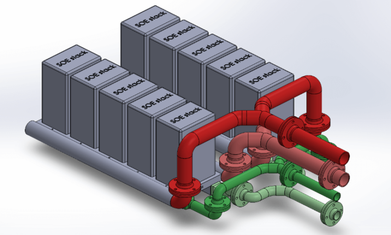
One of the challenges encountered when upscaling electrolyzer technologies from a single stack to multiple stacks is to achieve a uniform flow distribution across the stacks while maintaining a pressure drop across the system as low as possible. Ensuring that each stack receives the same amount of fuel and air is vital for efficient hydrogen production. It is thus important to carefully design and optimize the electrolyzer unit’s fuel and air distribution systems early in the design process to maximize its performance. Parameters such as size, shape, and orientation of the fuel and air flow channels are all relevant to investigate, but building and testing prototypes with different geometrical configurations would take too long and be too costly in early design stages.

Solution

Modelling Approach

To address the challenge of achieving uniform fuel and air flow distribution across the stacks of the electrolyzer unit, a CFD analysis was conducted. A few key modelling assumptions were made:

  • Individual stack pressure drop: A pressure drop was introduced into the system for each individual stack. Instead of directly modelling each stack, a two-way coupling approach was employed. This approach couples the velocity and pressure between the stack inlet and outlet on each side of the fuel/air distribution system.
  • Pressure Drop Estimation: The pressure drop across each stack is a function of flow rate and was prescribed based on experimental data from an earlier project. This dynamic pressure drop allows a good representation of the change of pressure across the stacks without having to solve a complex fully-coupled Multiphysics problem for each stack.
  • Gas Composition: The gas composition was assumed to remain constant throughout the analysis, as the focus was primarily on achieving uniform flow distribution.
  • Stack model: In the current approach, the stacks themselves were not explicitly modelled. However, it would be possible to relax some of the above assumptions by coupling the current model with a stack model. For example, the 3D homogenized stack model discussed in a previous blog post has the benefits of solving all relevant physics at a relatively low computational cost.

Studies

When the electrochemical reactions occurring within the stacks are not explicitly modelled, the fuel and air sides of the system are decoupled. Therefore, separate CFD analyses were done for the fuel and air sides:

  • Fuel Side: The objective was to determine the optimal orientation of the stack inlet pipes to achieve uniform fuel distribution between the stacks and minimize the pressure drop across the system. Two different designs were compared.
  • Air Side: The size of the air flow channels proved to be a critical factor in achieving uniform air flow distribution. Initially, equal-sized channels resulted in higher flow non-uniformity. To address this, a parametric study was conducted, varying the size of the air flow channels. The final design was obtained by optimizing the channel size while keeping the channel orientation unchanged.
Rescaling of the air flow channels

Result

The CFD analyses provided valuable insights into the flow distribution and pressure drop within the electrolyzer unit. The results from the studies conducted on the fuel and air sides are as follow:

  • Fuel Side: The comparison of different designs for stack inlet pipe orientation helped identify the configuration that offered better fuel flow uniformity across the stacks while minimizing the pressure drop in the system.
  • Air Side: The parametric study revealed that equal-sized air flow channels initially resulted in higher non-uniformity. However, by optimizing the channel size, uniform air flow distribution was achieved without changing the channel orientation.
Velocity streamlines on the fuel side
Figure 3: Velocity streamlines on the fuel side
Mass flow distribution across the stacks on the air side (a) before rescaling,

a)

Mass flow distribution across the stacks on the air side (a) before rescaling, and (b) after rescaling of the channels.

b)

Figure 4: Mass flow distribution across the stacks on the air side (a) before rescaling, and (b) after rescaling of the channels.